Its been a while but other projects have been taking my time so progress has slowed on the decoder.
The LCD display described in previous posts was used to minimise the Arduino processing time needed to output the decoded text. By driving the data lines directly, I was able to break the required code into small sections that could be readily processed in the program timeslots. The downside it that a single line display limits the amount of information that can be presented to the user.
Nextion display
I came across the Nextion displays and put one on my Christmas list to play with: The Nextion displays come with an integrated processor that looks after display formatting and updates whilst providing a simple serial interface for commands and data from the host device. This is ideal for using with the Arduino as the Nextion also provides data storage for storing display programming data, graphic files and fonts.
The downside of the Nextion display is that it is expensive and has its own coding requirement to set it up for each application. The coding is made easier with a free visual editor program although this is Windows only at present.
The serial interface is simple to use but one of the problems I came across whilst using the Arduino IDE for displaying diagnostic information is that the Serial.Print function takes a minimum of around 80μs to print a number. This is not a problem for printing characters as the Serial.Write function is actually very fast - it is the arithmetic for the conversion from a number to printable characters that takes the time. The problem arose when I wanted to print the numeric information: volume, frequency and words per minute to the Nextion display.

The solution I found was to minimise the Arduino conversion processing by sending the numeric data as hexadecimal characters (see Arduino code box). As the display processing is not so time sensitive, the Nextion could be used for the more complex task of converting the hex into a displayable number.
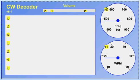
The display format I created includes a multi-line section for the decoded text, a linear volume bar and 2 circular dials for the carrier frequency and the words per minute.
Text display
The Arduino decodes the characters and sends them one by one to the display using the Serial.Write function to send the Ascii value. The Nextion display allocates the incoming character to the nominated variable (cw.txt) but this needs to be processed before the relevant display variable (t0) can be updated. to refresh the display. However, the routine to do this processing needs a trigger event so a dummy display touch event is also sent by the Arduino to initiate the processing - see Nextion serial commands box.

The text processing routine adds the incoming character to the display variable for the text string displayed in the bottom line of the decoded text section. it also checks to see if a line feed is needed and, if so, moves all the text up 1 line. Initially, I used the Nextion to count the characters and insert a line feed instead of the most recent space when the count exceeded the line length. This worked fine for a fixed width font but I wanted to use a better looking font with proportional spacing.
The Nextion instruction set and variables didn't have the flexibility I needed to code for this so I pushed the linefeed calculation back to the Arduino. I created an array of pixel widths for each Morse code character and summed these instead of simply incrementing a character counter. When the number of pixels exceeded the line length, I sent an otherwise unused character (lowercase L) to the Nextion. The Nextion routine retained the task of determining where to insert the line feed and which characters to carry over to the next line. The older text is scrolled up the display field through display text variables t1 - t6.
I also used the Arduino Morse code space timing to insert a linefeed if the break in decoded characters significantly exceeded the word space time.
Signal parameters
The Arduino CW decoder program already included variables that tracked the input volume level, the carrier frequency and the decoded words per minute but these were not held in units that would mean anything to the user. The first task was to convert these to values into the range 0-255 so that they could be sent to the Nextion display as 2 hex characters.(00-FF). The processing and scaling of these values for the relevant output display variable is then completed by another Nextion routine. This is triggered by a timer in the Nextion to provide a consistent refresh every 2 seconds.
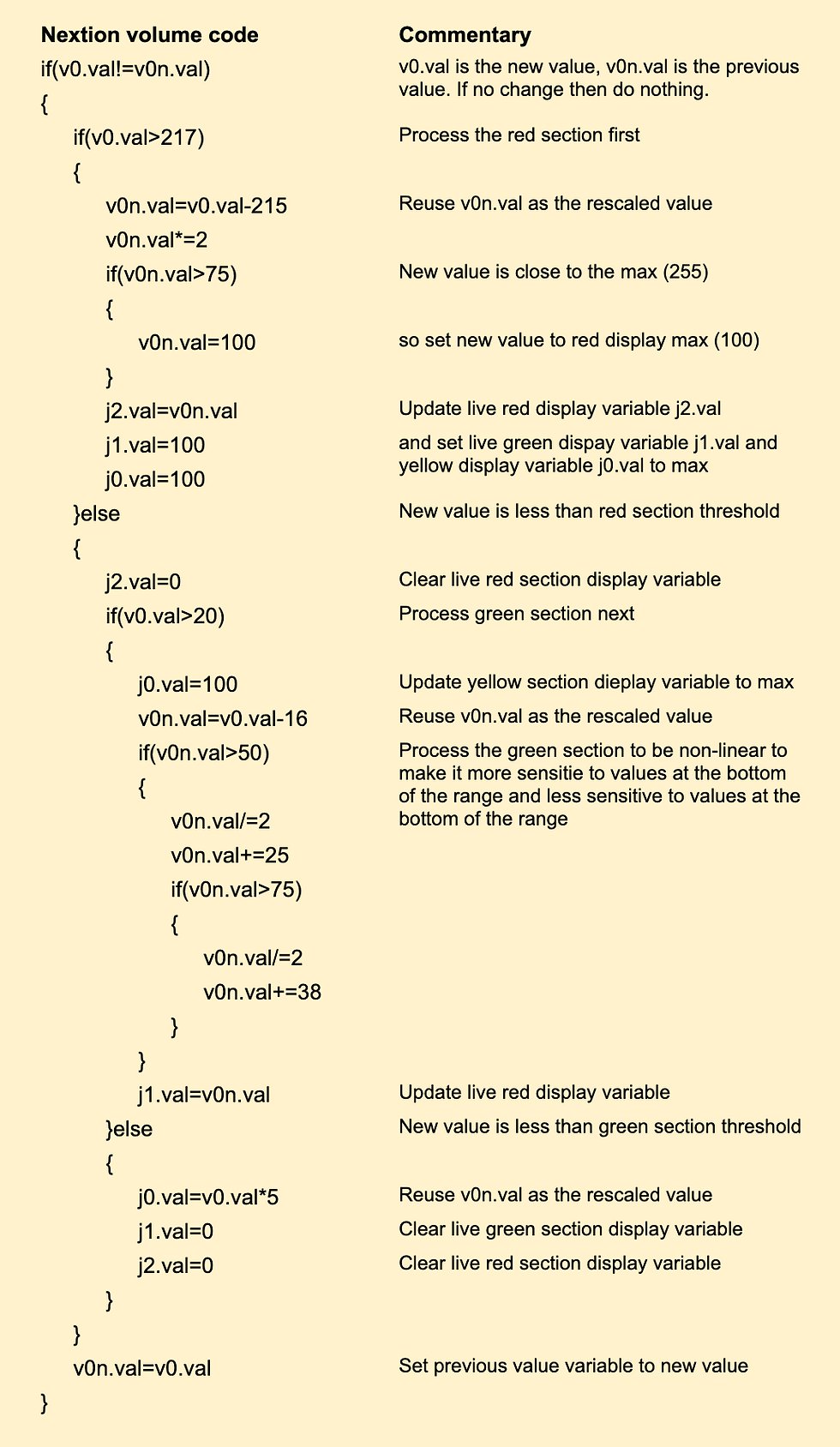
The Nextion provides for linear bar indicators scaled from 1-100 with a single colour. The volume indicator uses 3 of these elements (jo, j1, j2) placed together to appear like a multicolour bar:
Volume too low (yellow) 0-20 => 0-100
Volume ok (green). 20-215 => 0-100
(non-linear)
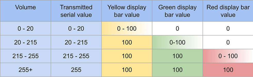
Volume too high (red) 215-255 => 0-100
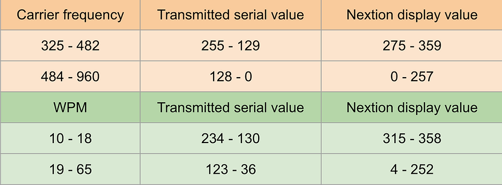
The Nextion dial display elements (z0, z1) take an input of 0-360 (degrees) and move the pointer over a custom image background.
The parameter values are sent by the Arduino every 16 * 255 processing cycles (which equates to 150 to 500 ms) using a separate print buffer to the one for decoded characters. Volume, carrier frequency and words per minute are received in Nextion variables v0, v1 & v2 respectively.
Performance
The Nextion display presents a much more useful interface for the CW decoder as can be seen in the video.
The disadvantages are the cost and the need for a bigger enclosure. The power requirement is also higher which means it would be less easily used as a portable device.
Other developments
The improved formatting of the Nextion display highlighted a few issues with the way that changes of sender (and associated changes in carrier frequency and transmission speed) were handled. To improve this I added another small buffer to capture the new carrier frequency in advance of decoding text for the new sender. This cures the loss of the first few characters of the new signal. I have also simplified and improved the CW timing capture to make it more reliable.
A future consideration is the use of the touch capability of the Nextion to provide the control interface. It could be used to pause the display and capture specific elements such as call signs but I have not done any work on this yet.
Reference
The specification of the Nextion display I used is NX4827T043 - 4" 480x272 basic series and more information can be found at https://nextion.tech/datasheets/nx4827t043/
The editor for the display code can be found at https://nextion.tech/editor_guide/
If you are interested in more detailed specifications, schematics and code then please contact me. Please note that I haven't got this in a professional format though.
Comments