CW training aid
resources and downloads
Hardware design
This section contains circuit schematics, PCB design and components.
ESP32
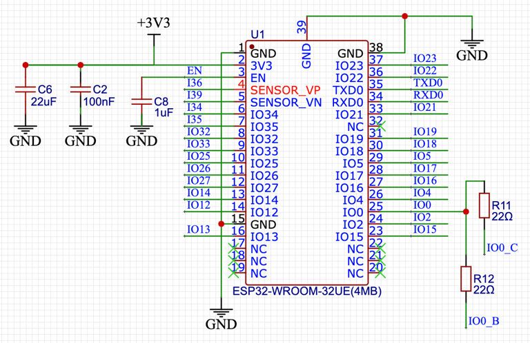
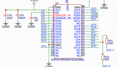
This ESP32 is at the heart of the circuit board. The basic surface mount processor requires several support circuits for power up, reset and programming via a usb socket. This external ESP32 circuitry is based on the application data sheets from the manufacturer's website: espressif.com
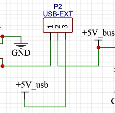
I have added an external power supply which is only needed if USB power is not sufficient and link P2 allows the appropriate input power to be selected. The buck converter (U4) can be omitted if the device is only to be powered from the USB connector.
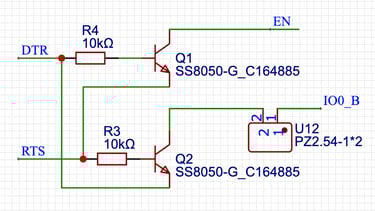
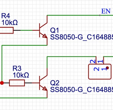
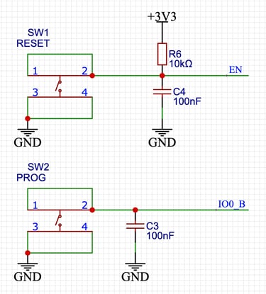
I found the auto program mode reset to be unreliable and added link U12 to allow this to be disabled. Program mode can still be selected by pressing switch SW2 on start up or the main control button on the device which uses the same i/o port.
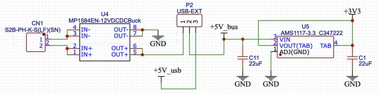
12V input to 5V converter, external/usb source selection link and 3.3V regulator
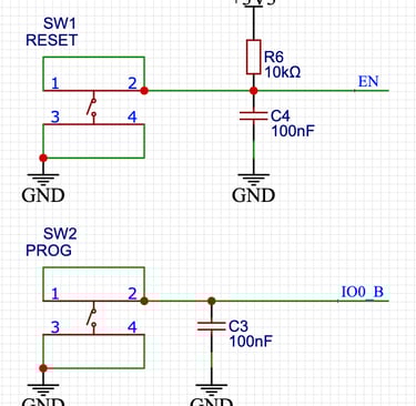
Reset and program buttons
Auto program mode reset
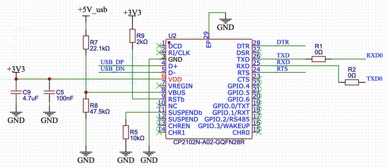
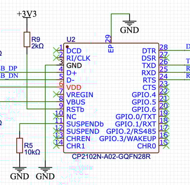
ESP 32 connections
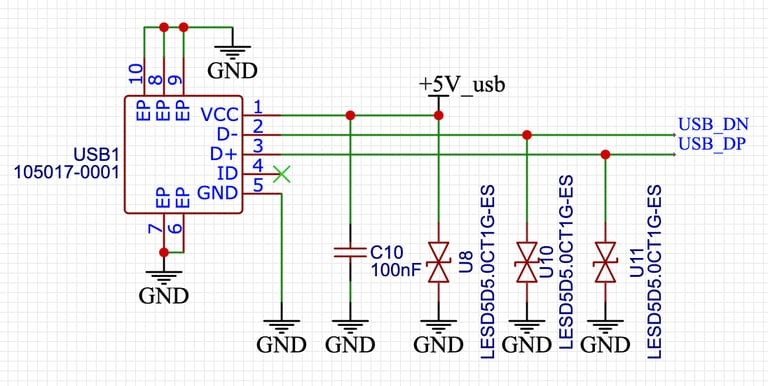
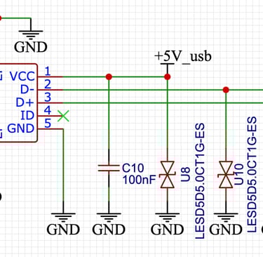
USB power/data connector
Serial communication UART
Audio input and output
The audio input circuits cater for direct connection using a 3.5mm plug/socket or for a microphone. If one type of input is not required then the relevant components need not be fitted.
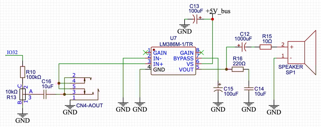
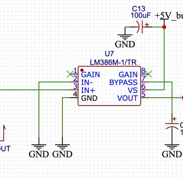
The audio output circuitry also caters for direct output as well as a built in speaker. If the speaker is not required then the relevant components can be omitted.
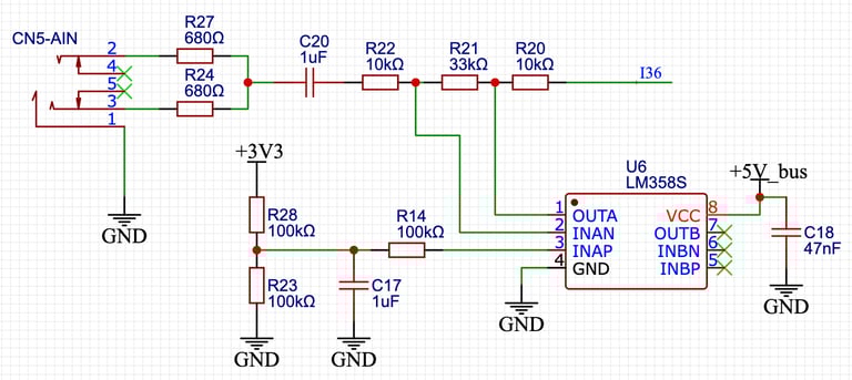
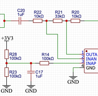
Direct audio input conditioning and amplifier
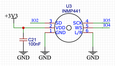
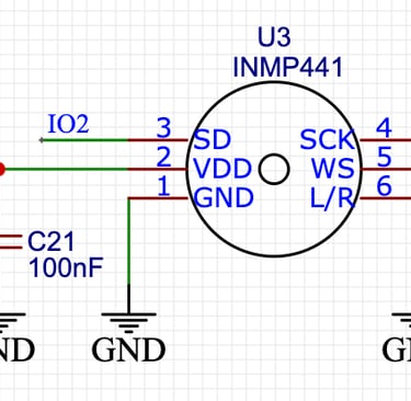
I2S MEMS microphone
Direct audio out connector, amplifier and internal speaker
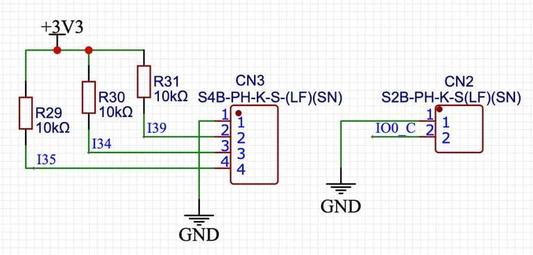
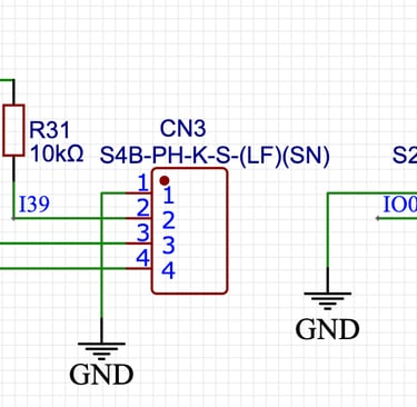
External connections
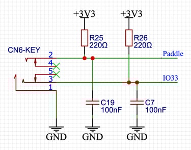
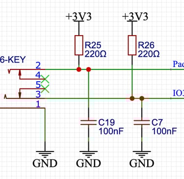
TFT, CW key/paddle, rotary encoder, button and optional gyroscope. The gyroscope is not needed for the CW trainer and doesn't need to be fitted. Link P1 is required and needs to be connected in the "key" position for the CW key or paddle to work.
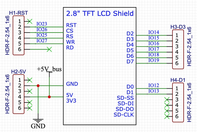
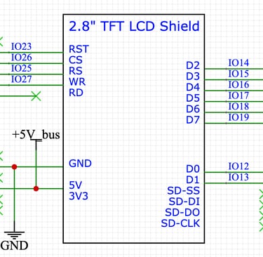
TFT display connectors
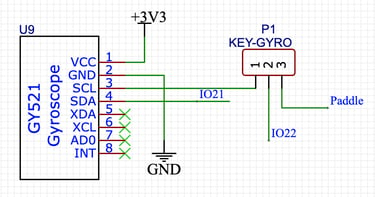
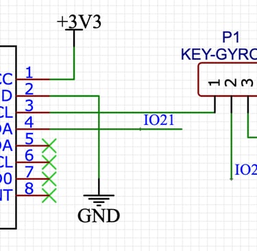
CW key/paddle
Rotary encoder and button connectors
Gyroscope and accelerometer
Software
This section contains flowcharts, code extracts and downloadable software images
Software download
The code is written in C++ using the Arduino IDE 2.3. More recent versions of the Arduino IDE have introduced a Arduino compiler for ESP32 boards but this does not support some of the functionality required for this project. In order to make any changes to the software I am continuing to use the ESP32 by Espressif Systems board manager at version 1.08.
In order to upload the software you will need the Espressif esptool: an open-source, Python-based utility designed by Espressif Systems for interacting with the ROM bootloader in ESP8266, ESP32, and later processors. This allows users to flash firmware, erase memory, read data, and configure chips via a serial port.
More information on the esptool can be found at https://docs.espressif.com/projects/esptool/en/latest/esp32/
and installation information can be found at https://docs.espressif.com/projects/esptool/en/latest/esp32/installation.html
The compiled software is available for download and non-commercial use.
The downloads button will open the Pro Antennas Google Drive in a new tab and the relevant files (ESP_CWdecoder_v7_1.ino.partitions.bin and ESP_CWdecoder_v7_1.ino.bin) can be downloaded by clicking on the 3 dots at the right of the file details and selecting download.
Once the esptool is installed. The software can be updoaded to your processor using the command line below.
/Users/tony/Library/Arduino15/packages000/esptool --chip esp32 --port "/dev/cu.SLAB_USBtoUART" --baud 921600 --before default_reset --after hard_reset write_flash -z --flash_mode dio --flash_freq 80m --flash_size detect 0xe000 "/Users/tony/Library/Arduino15/packages/esp32/hardware/esp32/1.0.6/tools/partitions/boot_app0.bin" 0x1000 "/Users/tony/Library/Arduino15/packages/esp32/hardware/esp32/1.0.6/tools/sdk/bin/bootloader_dio_80m.bin" 0x10000 "/Users/tony/downloads/ESP_CWdecoder_v7_1.ino.bin" 0x8000 "/Users/tony/downloads/ESP_CWdecoder_v7_1.ino.partitions.bin"
Notes
The command should be entered as 1 line with each line break being a space character.
The file paths (red text) are the defaults if the esptool is installed on an Apple Mac using the Arduino IDE ESP32 Espressif board manager. These will need to be changed to match the respective paths for your installation.
If the boot_app0.bin and bootloader_dio_80m.bin files are not part of your esptool package then these can also be downloaded from the Pro Antennas Google Drive.
The port definition (blue text) is specific to a serial over USB port on the Apple Mac and may need to be changed to match your installation.
The quotation marks around filename paths are only required to ensure that any spaces in folder and file names are not treated as command separators. I have left them in incase they are required for your installation.
Support
proantennas@gmail.com
+44-7470 337050
© 2025. All rights reserved.