Arduino mini oscilloscope
Apr 2020
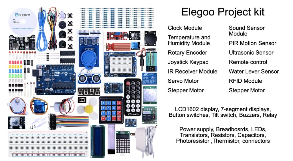
After thinking about getting a microprocessor to play with last year, I finally got an Arduino kit for Christmas 2019. It came with a wide range of components, sensors, displays, servos, motors etc and I spent the first month or so working through the tutorials to get back into programming (after 30+ years).
I then started thinking about a project of my own to take on and decided an oscilloscope would be useful, especially for debugging other projects I had in mind. There were a few examples online and I took some ideas from them and started working on a design.
The first task was to get the Analogue to Digital Converter (ADC) working sufficiently quickly to give a meaningful frequency range. Realistically, I was only expecting to cover audio frequencies so it shouldn’t be too challenging.
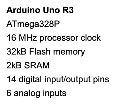
The Arduino Uno R3 has a 16Mhz clock but the ADC works by a process of successive approximations and takes 13 cycles to complete a conversion. It also needs time for the sample to settle so the clock is divided by a default value of 128 to give 10 bit accuracy. This gives a theoretical sample rate of 9,600 sps.
To speed things up I modified the clock divider value in ADC Control and Status Register A (ADCSRA). I also used a direct read of the register to indicate when the conversion is complete and retrieve the value. This is quicker than using the Analog Read function.
A maximum sampling clock frequency of 200kHz is recommended for full 10 bit accuracy but, as I only wanted 8 bit resolution, I decided that a divider value of 16 - giving a sampling clock frequency of 1MHz - was acceptable.
Running a test over 1000 samples confirmed that the sampling was completed in 15uS and that the 8 bit accuracy was unaffected by the increased sampling clock frequency.
The next step was to find a suitable way of displaying the result. One option was to send the data over the serial link to a computer and use another program to process it into graphical form. I decided against this because:
I could only find suitable processing software for Windows and I’m using a Mac
I was wanting a standalone, portable oscilloscope
The serial link processing would probably limit the screen update rate
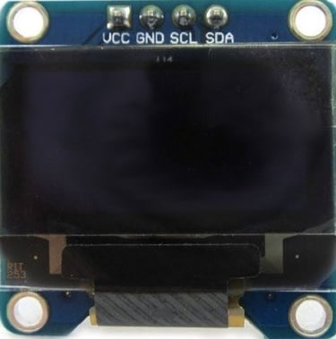
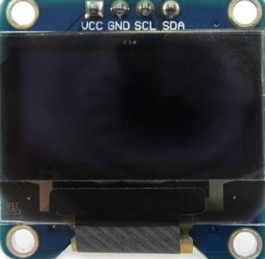
To keep the cost down, I decided to use a small (1.3”) monochrome OLED display with an I2C (Inter Integrated Circuit) interface. I found one on eBay that was very cheap but I then spent several days trying to get it to work before deciding it was dead - if only I had an Oscilloscope to diagnose the problem!
A second one from Amazon cost a little more but worked fine. However, the SH1106 driver library was very large and slow so I studied the data sheet and, eventually, worked out how to program it directly. I also found how to increase the I2C bus speed by modifying the TWBR register and ended up with a full screen refresh time of 40mS. This is still quite slow relative to the sampling speed but is adequate for my requirement. I may look at using an SPI interface to speed it up in a future development.
SH1106 OLED display
The display is only 128 x 64 pixels which means that an 8 bit ADC resolution (0 - 255) is more than adequate for a height of 64 pixels by a factor of 4. The width of 128 pixels dictated the settings for the timebase which can be seen in the table.
To prevent aliasing on the slower timebases, instead of slowing the sampling rates, I over sampled and combined the results to give a high-low vertical bar on the display.
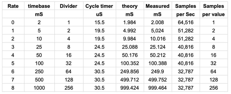
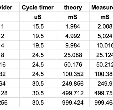
Sampling rate calculations for setting the Arduino oscilloscope timebase values
To avoid cluttering the limited display space with range, timebase and trigger options, I created a separate menu page for the settings. The currently included options are:
Range: Initially just 5vdc. I may add hardware to handle ac input and provide more range options in a future development.
Timebase: The display width is set to accommodate 2mS, 5mS, 10mS, 25mS, 50mS, 100mS, 250mS, 500mS and 1s.
Trigger: Rising edge, Falling edge, Manual and Free-run.

Setting oscilloscope parameters on the Menu page
In future developments I intend to add a top level select option to the menu screen that will allow switching from an oscilloscope to other functions - yet to be decided.
I like the feel of rotary encoders so I decided to use 2 of these to control the selection of the required parameters. The left encoder moves the selection up and down between the option fields and the right encoder scrolls through the available parameters for each option field. A small button is used to switch between the Menu screen and the oscilloscope display.
Whilst the oscilloscope is running, the trigger level can be adjusted with the left encoder and the current trigger position is indicated by a small block on the left side of the screen. Pressing this encoder over-rides the trigger hold in auto and manual modes.
The right encoder changes the timebase and the current value is indicated in the bottom right corner of the screen.
The operation is demonstrated in this video:

Changing settings in run mode
The oscilloscope has been assembled and tested on a breadboard - as can be seen in the videos. The connections are shown on the schematic diagram below. Note that the SH1106 display is powered from a 3.3V supply (provided by the Arduino board) and the pull up resistors for the SCL and SDA signal lines are also connected to this rail. I Initially used the 5V supply but had some problems with the I2C interface hanging, especially with the increased bus clock speed. The lower voltage and external pull up resistors cured this problem.
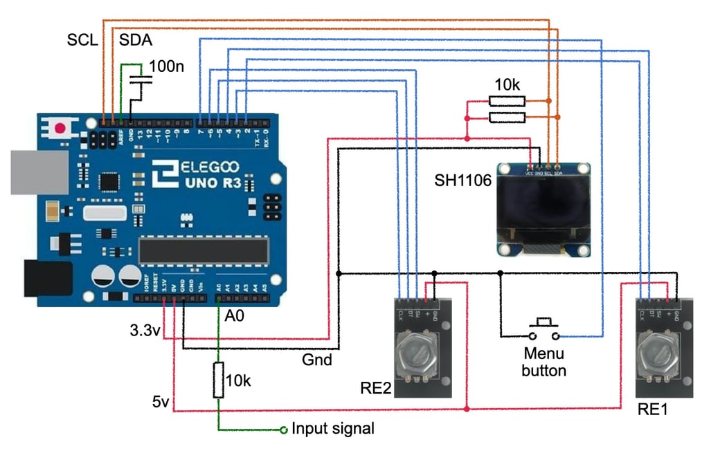
The oscilloscope could easily be built into a small plastic box to provide a fully portable and self contained solution.. I am looking at other development possibilities before finalising the design and, for now, am happy with using it in the prototype form.
I have several ideas for future development which may be expanded on in future posts. These include:
Alternative displays to improve the refresh rate and maybe increase the screen size
Additional functionality in the same package such as a DVM and spectrum analyser
AC input ranges
Additional ranges using op amps for less than 5V and voltage dividers for higher range
I would be happy to hear views on other possibilities for consideration or any comments and suggestions.
Downloads
The Arduino source code is available to use and modify. It was written using the Arduino IDE and was last updated on version 2.3.0 of the IDE. Please note the code is not professionally written or documented but I am happy to answer any questions that may arise.
The downloads button will open the Pro Antennas Google Drive in a new tab and the relevant file (Oscilloscope_18) can be downloaded by clicking on the 3 dots at the right of the file details and selecting download.
Support
proantennas@gmail.com
+44-7470 337050
© 2025. All rights reserved.