ESP32 CW decoder/trainer
January 2025
I first developed a CW decoder using a newly acquired Arduino microprocessor at the start of the Covid lock down. After successfully building a mini oscilloscope, and still needing something to occupy my time, this seemed like a good learning challenge.
The project was successful and I learned a lot in the process but the limited speed and memory of the Arduino meant some compromises had to be made. I looked at more powerful processors and eventually chose to re-engineer the project using the Espressif ESP32S.
This turned out to be a long term project and involved several changes of scope to add more functionality. I am now at the point where I am happy with the outcome and believe that it is an achievement that is worth sharing.
Note: this project write up is not yet complete
19 Jan: hardware resource circuitry details added
Overview
This device, in its latest form, provides 4 modes which are all designed to help beginners learn, practice, decode and analyse morse code transmission.
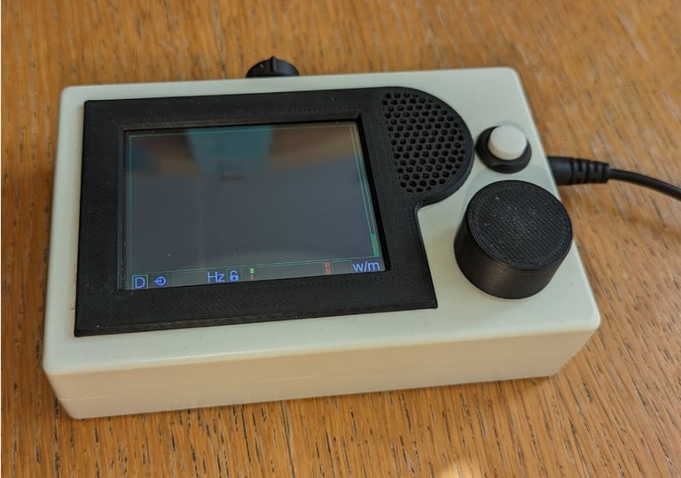
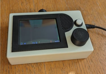
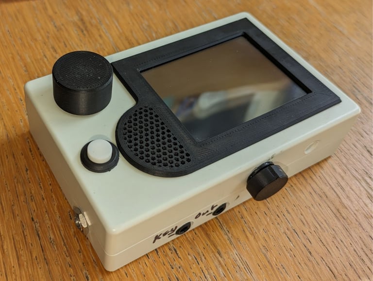
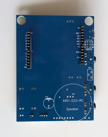
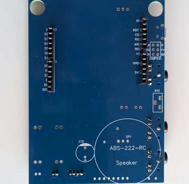
The hardware comprises an ESP32S interfaced to a 320x240 colour LCD display. Audio CW can be received through an on-board microphone or directly from a receiver or computer via a 3.5mm socket. A small on-board speaker provides audio feedback for sending practice and, alternatively, a second connector allows the audio to be played over an external speaker.
The user interface consists of a rotary encoder and a single button to select and confirm the required actions on the display. A third connector provides for a cw key or paddle to be connected for send practice.
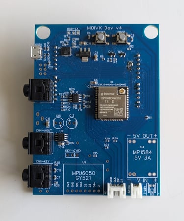
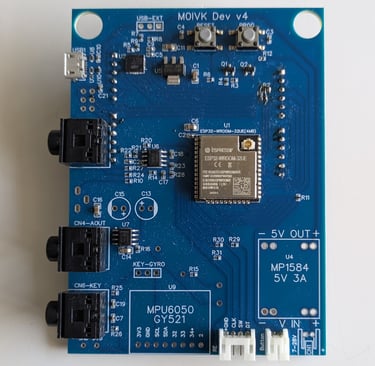
All the interfacing circuitry is mounted on a custom PCB with the processor, peripherals and a DC-DC converter.There is also provision for an accelerometer/ gyroscope module to be fitted to the board although this is not required for this project.

The software is written in C++ using the Arduino IDE with the Espressif compiler add-in. There is minimal use of libraries to increase performance and protect against updates causing issues. I am happy to share the compiled code and most of the source code but the CW decoding algorithm source code will not be made public - to try and prevent lots of clones appearing on eBay.
Operation
On initial start-up, the system reads any saved settings from non-volatile RAM. If this is the first start-up then a self calibration is performed and default settings saved. Ongoing calibration of the analog to digital converter is automatic.
After the opening screen, the previously saved default mode screen will be displayed. All the mode screens have a bar at the bottom for settings. Decoded text is displayed at the top of the screen and for the Decoder and Receive Practice modes the text area will use the whole of the remaining display area. For the Send Practice and Analysis modes the centre of the display is used for the relevant graphical information.
The rotary encoder dial is used for navigating the settings and a yellow highlight box will indicate the current selection. If there are just 2 options for the selected setting then pressing the dial will toggle the state. Where there are more than 2 options, pressing the dial will change the highlight box to red and allow the dial to be used to scroll through the options or values. Pressing the dial again will confirm the selection and return the highlight to yellow.
The left hand item on the settings bar is always the mode selection which is used to change mode.
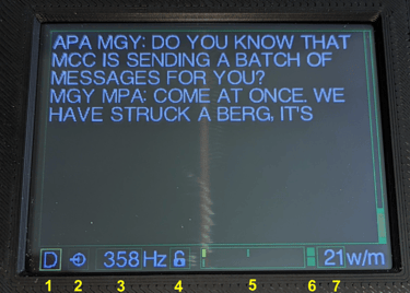
Decoder mode
The decoder takes an audio signal from the built-in microphone, or a direct output from a receiver/computer, and displays the message text in real time. The signal sampling rate is high enough to allow the carrier frequency to be measured and used to set the filter algorithm parameters to minimise the impact of noise and interference. If the signal is too noisy for the carrier frequency to be reliably detected, the filter frequency can be locked and set manually as required.
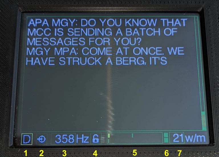
An adaptive threshold detector is then used to measure the signal on/off times over a wide range of signal amplitudes. These are buffered whilst the decoder works out the average dot, dash and space periods and hence the words per minute (wpm). This timing information is then used to decode the buffered signal and catch up to the real-time signal The time taken to start decoding depends on the mix of dots and dashes in the signal but the algorithm is optimised to give the best compromise between speed and accuracy.
The timing detector adapts to variations in the message rate and re-trains after a break or a carrier frequency change which is likely to be due to a different sender. The decoded text is displayed over 11 lines on the screen and scrolls up when this is filled. 256 lines of text are stored and these can be reviewed whilst the real time signal is still decoding.
The display functions are:
1 Mode select - to leave Decoder mode and select another mode.
2 Input signal source - to switch between the built-in microphone and an external source.
3 Carrier frequency - detected automatically or manually set.
4 Frequency lock - to allow the carrier frequency to be set manually.
5 Audio level monitor - the top bar is the audio level and the bottom bar is the noise level.
6 Signal detect indicator - the top box turns green when the cw timing is determined and the bottom box turns green when the carrier frequency is detected.
7 Words per minute - measured transmission rate.
Receive Practice Mode
In this mode the device generates an audio stream of random CW characters for decoding practice. An interpretation of the Koch method is used - the number of different characters being sent is gradually built up as each character is learned. The characters are displayed on the screen for checking the accuracy of transcription. The text display area is the same area used for Decoder mode and the same review functionality is available.

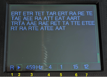
The characters to be sent are selected on a set up screen where each character can be marked as learnt, in progress or still to be learnt. The characters are listed in the recommended order for learning but this can be changed as required. The characters marked as in progress will be repeated more often than the learnt characters to speed up learning whilst maintaining the memory of learnt characters.
The sending rate (wpm) can be set independently for both the character and the inter character space. This helps the user recognise the character pattern at a realistic speed but allows more time for assimilation of each character until this becomes automatic. The length of each session can also be varied with a range of 1 - 4 minutes.
The audio can be heard on the internal speaker or connected to a headset or external speaker using the 3.5mm output connector.
The controls for this mode are:
1 Mode select - to leave Receive Practice mode and select another mode.
2 Play/stop - to start playing or stop before the end of the session time.
3 Carrier frequency - this can be set to the required tone.
4 Session setup - to bring up the character selection screen and save progress.
5 Duration - to set the session duration in minutes.
6 Character speed - set required speed wpm equivalent.
7 Inter character speed - set inter character space as a wpm equivalent.
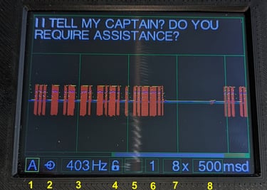
Send Practice Mode
Once some CW characters have been learnt, this mode can be used to refine your skill at transmitting. The device accepts a standard straight key or a paddle. WIth the straight key the user is responsible for the timing of the dots, dashes and spaces whilst the paddle input is set to automatically control the timing of the dots and dashes.

The send practice controls are:
1 Mode select - to leave Send Practice mode and select another mode.
2 Key type - select straight key or paddle.
3 Carrier frequency - this can be set to the required tone.
4 Target wpm - set the reference keying rate.
5 Wpm lock - switch on/off actual keying rate tracking.
6 Dot/dash wpm - measured equivalent transmission rate for key presses.
7 Space wpm - measured equivalent transmission rate for spaces.
8 Wpm - measured overall transmission rate.
The display scrolls from left to right and has a review mode that allows the user to scroll back through the recorded data. In review mode the decoded character is shown above the dot/dash/space timing marks for that character so that any errors can be identified and corrected. The keyed characters are decoded using the set target wpm and displayed in a 3 line widow at the top of the screen. The rest of the display uses a graphical format to show the timing of each key press and space and indicate how accurate they are relative to the desired rate timing.
The target wpm rate can be set as desired and there is an option to set this rate as a constant reference or let it adapt to the measured user transmission rate. The equivalent wpm for dot/dash and space timings are displayed separately to provide an accuracy overview.
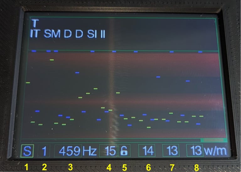
Analysis Mode
The analysis mode was initially an adaptation of my oscilloscope project that was used to develop the CW decoder. It provides a graphical representation of the signal and associated parameters at each stage of the decoding process for debugging and tuning of the algorithms. I have left it in the current decoder version as it provides an interesting window into the way the decoder works and shows why any decoding errors may have occurred.
The display format is similar to the Send Practice mode with a 3 line window at the top for decoded text and a graphical display in the main section of the screen.The display scrolls from left to right and has a review mode that allows the user to scroll back through the recorded data.

The speed of the display can be set to the required level of detail and the magnification of the displayed traces can be changed. There are up to 3 parameters displayed in different colours in each display option.
The parameter options include:
Audio signal + max, mid, noise level or frequency detect threshold.
Frequency detect parameters and algorithm output.
Filter algorithm output + noise or thresholds.
Dot/dash timing and threshold or deviation from threshold.
Space timing and threshold or deviation from threshold.
Dot/dash/space timing comparison.
The analysis mode controls are:
1 Mode select - to leave Analysis mode and select another mode.
2 Input signal source - to switch between the built-in microphone and an external source.
3 Carrier frequency - detected automatically or manually set.
4 Frequency lock - to allow the carrier frequency to be set manually.
5 Filter band - indication of the automatically set filter band.
6 Display option - to select the required graphical display.
7 Magnification - to set the magnification factor for the displayed values.
8 Speed - to set the display speed in ms per division.
Hardware
The original design for the CW decoder consisted of an ESP32S development board mounted on stripboard with connections for the display and additional circuitry for the audio input. I found this to be a little unreliable so, once I had a working prototype, I designed a custom PCB using EasyEDA and had it manufactured by JLPCB. I initially housed the assembled PCB in an enclosure from eBay but this required a lot of cutting to accommodate the display and connectors so I developed my own version using OnShape and a 3D printer which made assembly a lot easier.
The PCB and enclosure went through several versions as i added the key input, a speaker and audio output for send and receive practice modes.After prolonged testing, I created a new PCB design using surface mount components, including the ESP32 chip, which I ordered ready built from JLPCB. This made assembly easier still as now all I had to do was add the connectors and larger components. This was a big step for me as I had no previous experience of working with surface mount components and especially the ESP32 circuitry. However, I was very pleasantly surprised to have only a couple of errors which I was able to track down and correct before getting it all to work fine!
Support
proantennas@gmail.com
+44-7470 337050
© 2025. All rights reserved.