Technical Information
This section provides technical information on the design, construction and performance of our antennas
Design
The design brief for the Dual Beam Pro and I-Pro Home antennas is to give the best performance possible for a wide range of HF bands whilst maintaining an unobtrusive and aesthetically pleasing profile. The underlying design is a based on a 5m dipole which is considered acceptable for mounting on a rooftop in a residential area or erecting in a small garden.
A simple 5m dipole is resonant between the 10m and 11m bands; it would, therefore, be too short for the 40m - 14m bands and too long for the 6m band. The resulting antenna is therefore non-resonant and requires additional components to optimise the design.
The addition of capacitive end loading elements has the effect of electrically "lengthening" the dipole. This could also be achieved by mid loading with inductance but capacitive end loading has 3 advantages:
It is more efficient, resulting in lower losses
Capacitive loading designs have a higher bandwidth
It increases the radiation resistance more than inductive designs
The only disadvantage is that capacitive end loading can increase the wind loading but this is not significant for the slimline Dual Beam Pro and I-Pro Home antenna designs.
An important part of the design was to utilise a balanced, centre fed dipole with a matching transformer/balun to connect it to the unbalanced coax. This offers a much lower noise solution than an end fed dipole and reduces the unintended RF radiation that could affect domestic electrical equipment - both very important considerations in a residential area with restricted space.
The non-resonant design means that the antenna offers a wide range of impedances across the relevant bands. The specified balun is also a 4:1 voltage transformer which brings the impedance range closer to the required 50 Ohms.
Many multi band HF antennas use additional elements and components to provide a better match for each of the required bands. We opted to use a different approach in order to keep our antennas simple, lightweight and visually unobtrusive: The Dual Beam Pro and I-Pro Home require an external ATU to tune the bands. Each approach is a compromise and the best option will depend on individual circumstances and requirements. Some of the advantages and disadvantages of our approach are examined below.
Dual Beam Pro and I-Pro Home
Advantages
Simple design - easy to assemble and install
Easy to maintain - no complicated set up required
Compact - low visual impact
Lightweight - low wind loading and easily rotated
Low noise
Disadvantages
Needs an external ATU to tune across all the bands
Some power is lost in the feeder
The Dual Beam Pro and I-Pro Home have been thoroughly tested using LDG ATUs and 25m of low loss RG mini 8 coax feeder. The feeder length is a compromise between efficiency and ease of tuning. A longer cable will result in higher losses but it will reduce the SWR seen by the ATU and make the antenna easier to tune.
The LDG Z11 Pro is ideal for operation up to 100W. To assess the suitability of other ATUs, a tuning range of 6 - 1000 Ohms is recommended for operation across the full range of bands.
As discussed above, the demand on the ATU can be reduced by increasing the feeder length, at the cost of greater power loss in the cable.
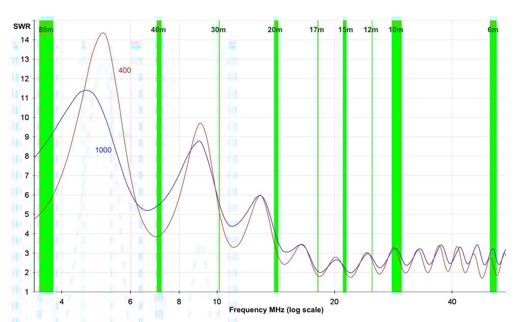
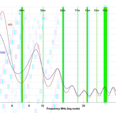
Typical SWR plots for the Dual Beam Pro 1000 and 400: Antenna height 4.5m, feeder length 25m
Notes
The efficiency of the antenna is reduced for the 40m and 30m bands due to the higher cable losses.
The antennas are not designed for 80m but reception may be possible at a reduced level.
The SWR may be affected slightly by the height and local environment
The SWR measurement will be affected strongly by the cable length/attenuation
The Dual Beam Pro and I-Pro Home are electrically identical and differ only in the mounting arrangements. The I-Pro Home can be readily reconfigured as a Dual Beam Pro whilst conversion from Dual Beam Pro to I-Pro Home will require a couple of additional mounting components that we can provide if required.
I-Pro Traveller and DMV-II
The I-Pro Traveller and DMV-II are intended for portable operation and have a very different design brief to the Dual Beam Pro and I-Pro Home. This application requires an antenna that can be readily transported and quickly set up without the need for tools or additional equipment. These antennas are designed to be resonant on the required band to avoid the need for an ATU and multi band operation is achieved by manual adjustment of the antenna.
The I-Pro Traveller has similar capacitive end loading elements to those of the I-Pro Home but the size is reduced further by adding a central loading coil with tapping points to adjust the number of turns. Fine tuning of the resonant frequency is enabled through adjustment of the angle of the lower capacitive end loading arms. A separate centre section with more loading coil turns is used for the 40m and 30m bands.
The DMV is a simple V shaped wire antenna with hanging element ends forming the distinctive M shape. Different sets of loading coils are used for the required band and plug in lengths of element wire are used for fine tuning of the resonant frequency.
The I-Pro Traveller includes an adjustable stand for ease of use but alternative mountings can be used so long as they use an insulated support rod. The antenna has be successfully deployed on balconies and vehicles using custom mounting arrangements. The mounting height doesn't need to be more than 1m above ground but it can be higher if this is convenient or there are local obstructions to overcome.
You may see variations in the angle of the arms needed to tune for a particular band when you are at a different location. The ground plane can affect the tuning especially on 40m and 30m. This is particularly noticeable if the ground is very wet or covered in snow and ice and can sometimes be make it difficult to tune sufficiently.
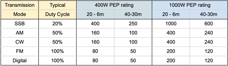
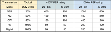
Power ratings
The antenna maximum power ratings are quoted as Peak Effective Power (PEP). This is a measure of the power of a radio transmitter during its peak transmission. It's the average power over a single radio frequency cycle at the crest of the modulation. This is important because it helps determine the maximum power output of a transmitter, which is crucial for ensuring regulatory compliance and minimising interference with other signals.
If we consider equipment with a maximum power rating then the duty cycle of the transmission mode is also important and is often the limiting factor as it determines the average power over a longer period of time.
The following table summarises the maximum power rating for the Dual Beam Pro and I-Pro Home using different transmission modes.
The I-Pro Traveller and DMV-II also have maximum power ratings but they don’t require a matching transformer so are less susceptible to overheating and core saturation.
Support
proantennas@gmail.com
+44-7470 337050
© 2025. All rights reserved.