Dual Beam Pro Specifications
The Dual Beam Pro is constructed from aluminium alloy tubes with an insulating GRP rod in the centre. A 4:1 voltage transformer provides a balanced to unbalanced interface to the feeder and transforms the impedance to give a broad match across the HF bands.
Physical
Length 5.0m (16ft)
Width 2.5m (8ft)
Turning radius 2.8m (9ft)
Weight 4kg (9lbs)
Peak Envelope Power (PEP)
Version 400 1000
Max 20 - 6m bands 400W 1000W
Max 40 - 30m bands 240W 600W
Radiation pattern
The Dual Beam Pro has 2 main radiation lobes transmitting perpendicular to the main elements.
The typical directional gain relative to a theoretical antenna radiating equally in all directions (Isotropic gain) is:
20m: 6.6dBi @ 29 degrees elevation
15m: 7.6dBi @ 19 degrees elevation
10m: 7.4dBi @ 15 degrees elevation
Requirements
The Dual Beam Pro requires an external ATU for operation across the full range of bands. For more information take a look at the design information.
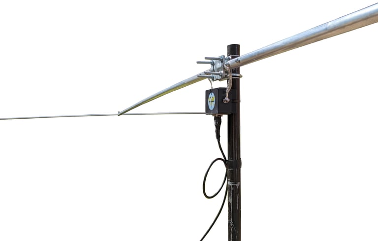
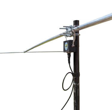
The mast head support bracket is suitable for 32 - 50mm (1.25 - 2 inch) diameter masts. The mast can be stand alone or a support pole attached to a building.
There is no minimum height for mounting the Dual Beam Pro but it should be at least 1m above ground and at least 1m away from other antennas mounted on the same support.
There is no maximum mounting height. Generally the higher the better for performance but the local environment will have a much greater influence. If you are at the top of a hill with clear views then the mast height will make little difference but if you are surrounded by buildings or other obstructions then a higher mast will be better.

Dual Beam Pro 400 / 1000
Assembly instructions
Contents
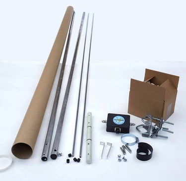
The packing tube should contain:
2 x 1 inch diameter alloy 2.5m main element sections complete with end caps and capacity hat securing bolts
2 x 3/8 inch diameter alloy 2.5m capacity hat elements
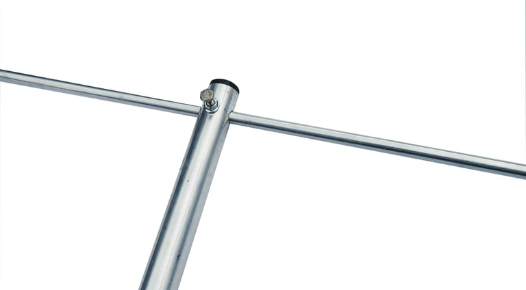
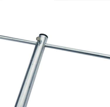
1 x GRP rod centre support insulator
3 x cable ties, 1 reusable stainless steel
The small box should contain:
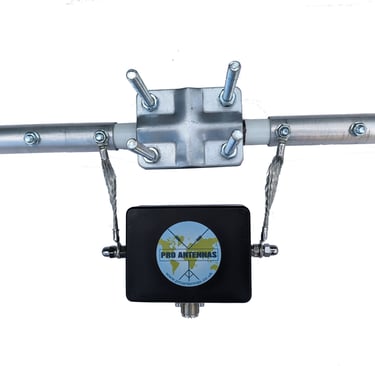
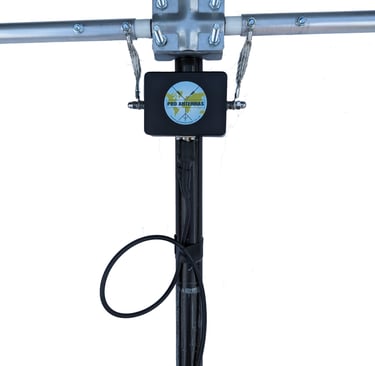
1 x matching transformer with mounting block
2 x matching transformer connection leads
1 x galvanised mast head support clamp
4 x 35mm M6 bolts with serrated nuts
4 x capacity hat element end caps
1 x self amalgamating tape for sealing the cable connector

Tools required
10mm and 13mm spanners
Safety
GRP/aluminium splinters can cause skin irritation and protective gloves must be worn before handling.
Ensure you have a safe working area of at least 5m x 3m.
Abide by the Work at Height Regulations for installation.
Assembly
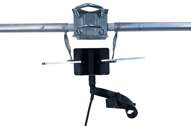
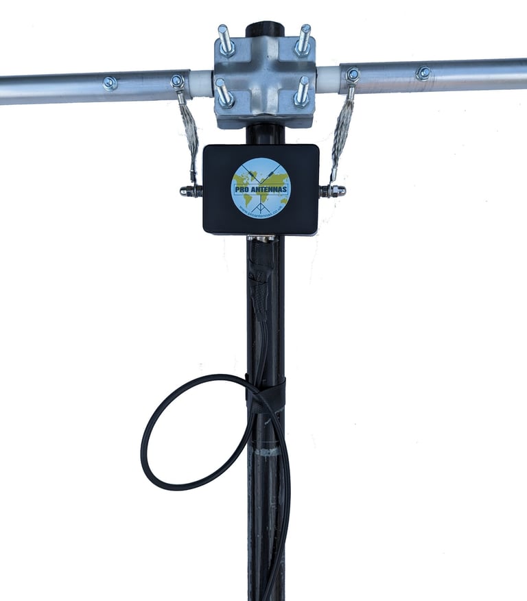
Note: these instructions show the 400W matching transformer. The 1000W version is orientated through 90 degrees but otherwise the same instructions apply.
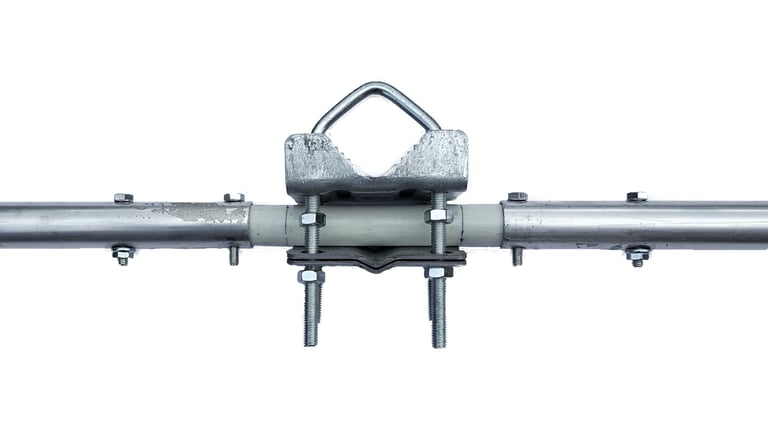
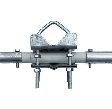
1. Insert the GRP rod through the section of the mast head support clamp but do not tighten the clamp at this point.
2. Fit the main elements onto the GRP rod and align the bolt holes. Ensure that the capacity hat securing bolts are both facing towards you before inserting the 4 x 35mm bolts and fitting the serrated nuts to the 2 outermost bolts.
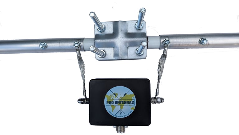
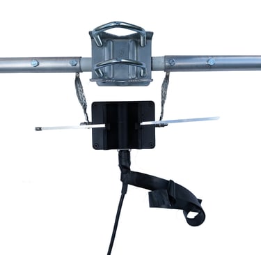
3. Fit the 2 connection leads to the matching transformer and offer up the assembly to the 2 innermost bolts. Fit the serrated nuts finger tight.
4. Slide a capacity hat element through the hole in the outer end of a main element section. Centralise the capacity hat element using the alignment marks and tighten the securing bolt by no more than 1/2 turn.
Fit the plastic end caps and repeat step 4 for the other capacity hat element.
The feeder can now be fitted to the matching transformer with a PL259 connector. Seal the connector against moisture using the self amalgamating tape. Remove the backing layer and wrap the tape tightly from the socket to the plug.
Slide the cable tie through the slot between the mounting block and the transformer housing. The spare cable ties can be used for extra security or kept for future use.
The antenna should now be aligned to give maximum coverage in the desired directions before fully tightening the mast head clamp bolts.
Finally, check that all the main element bolts, matching transformer connection lead nuts cable ties are tight.
Lift the antenna onto the support mast and tighten the cable tie(s) to secure the matching transformer to the mast.
Ensure that the mast head clamp is still central on the GRP rod and that the capacity hat elements are horizontally aligned before finger tightening the mast head clamp bolts.
Form a small loop prior to taping the coax cable to the support mast using insulating tape. If you are using a rotator, ensure there is enough slack in the cable to allow the mast to rotate without restriction.
The Dual Beam Pro is bidirectional in that it radiates 2 lobes at right angles to the main element and it should be installed with the lobes pointing in your preferred transmission/reception directions. The gain is not so great that you notice a marked improvement in performance but If you want more flexibility to transmit/receive in other directions at times then a lightweight rotator will ensure that you are getting the maximum performance from the desired locations.
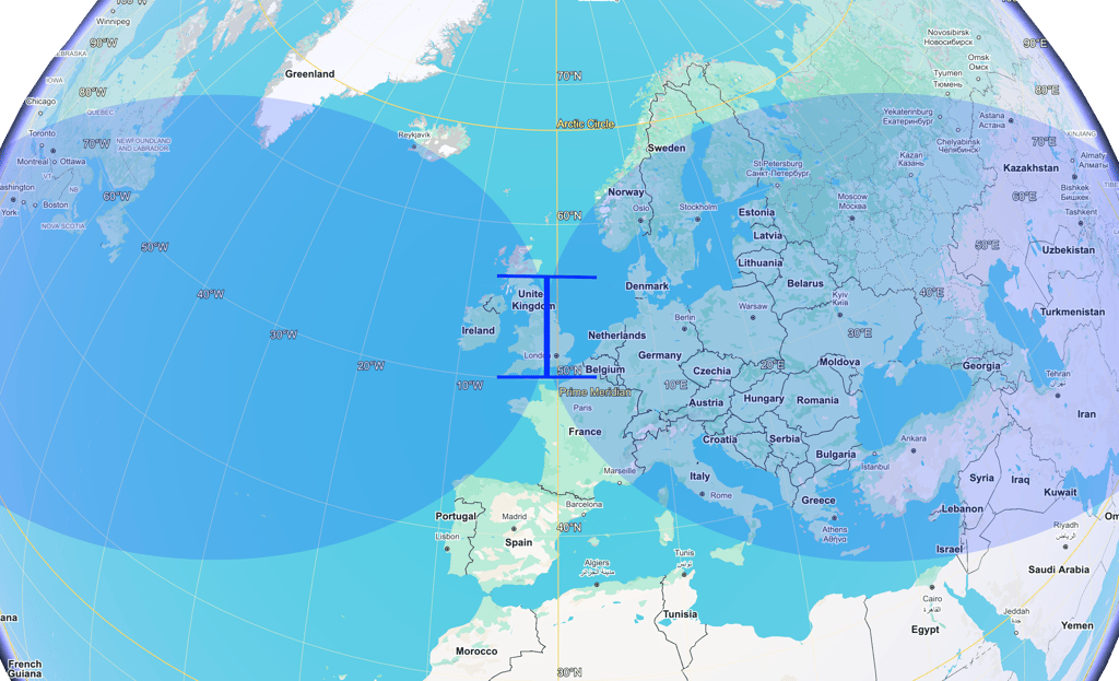
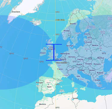
This diagram shows a Dual Beam Pro located in the UK with an East/West orientation. The radiation pattern is indicative for directional information only.
Note: Google Earth is a useful tool for planning the required orientation of your antenna.
Support
proantennas@gmail.com
+44-7470 337050
© 2025. All rights reserved.