I-Pro Home Specifications
The I-Pro Home is constructed from aluminium alloy tubes with an insulating GRP rod in the centre. A 4:1 voltage transformer provides a balanced to unbalanced interface to the feeder and transforms the impedance to give a broad match across the HF bands.
Physical
Height 5.0m (16ft)
Width 2.5m (8ft)
Turning radius 2.8m (9ft)
Weight 4.5kg (10lbs)
Peak Envelope Power (PEP)
Version 400 1000
Max 20 - 6m bands 400W 1000W
Max 40 - 30m bands 240W 600W
Radiation pattern
The I-Pro Home is omnidirectional with a launch angle around 20 degrees
Requirements
The I-Pro Home requires an external ATU for operation across the full range of bands. For more information take a look at the design information.
The I-Pro Home requires a ground post (not included) with a diameter of 32 - 50mm (1.25 - 2 inch) and a height above ground of 1m.
There is no maximum height for the I-Pro Home but the practicalities of lifting the antenna onto the ground post and guying it become more difficult if it is higher.There is little performance advantage in raising the height - it is more important to keep the installation a reasonable distance from buildings and other obstructions.

I-Pro Home 400 / 1000 Assembly Instructions
Contents
The packing tube should contain:
2 x 1 inch diameter alloy 2.5m main element sections, 1 complete with end cap and capacity hat securing bolt
2 x 3/8 inch diameter alloy 2.5m capacity hat elements
1 x GRP rod centre joining insulator
1 x GRP rod base support insulator, complete with jubilee clip retainer
1 x 1 inch diameter 300mm centre support arm, complete with end caps
3 x cable ties, 1 reusable stainless steel
The small box should contain:
1 x matching transformer with mounting block
2 x matching transformer connection leads
1 x galvanised base support clamp
2 x cross clamps for the centre support and lower element
4 x 35mm M6 bolts with serrated nuts
4 x capacity hat element end caps
1 x self amalgamating tape for sealing the cable connector
1 x guying ring
Tools required
10mm and 13mm spanners
Safety
GRP/aluminium splinters can cause skin irritation and protective gloves must be worn before handling.
Ensure you have a safe working area of at least 5m x 3m.
Abide by the Work at Height Regulations for installation.
Assembly
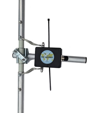
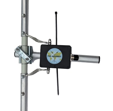
Note: these instructions show the 400W matching transformer. The 1000W version is orientated through 90 degrees but otherwise the same instructions apply.
1. Attach the central GRP rod (with 4 drilled holes) to the centre support arm bracket as shown and tighten the clamp nuts.
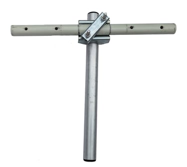
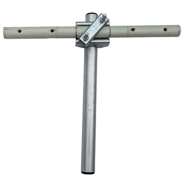
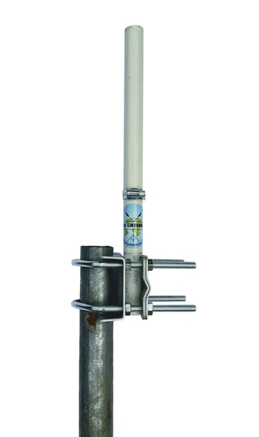
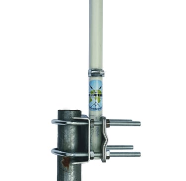
2. Fit the main elements onto the ends of the GRP rod and align the bolt holes. Insert the 2 outermost 35mm bolts and tighten the serrated nuts. The top main element section (with the end hat securing bolt) is on the right in the picture.
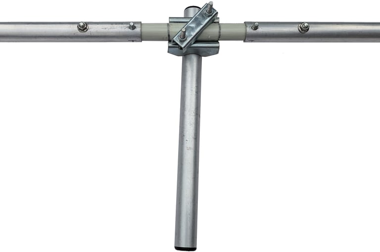
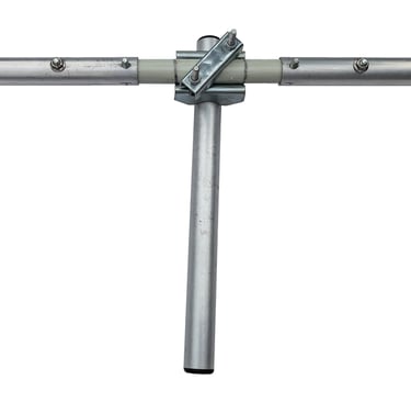
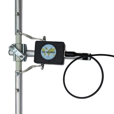
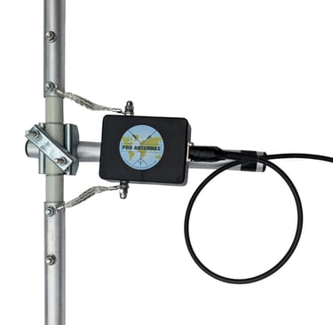
3. Fit the 2 connection leads to the matching transformer and offer up the assembly to the 2 innermost bolts. Fit the serrated nuts finger tight.
Slide the cable tie through the slot between the mounting block and the transformer housing and secure the assembly to the centre support arm. The second cable tie can be used for extra security or kept as a spare.
4. Slide a capacity hat element through the hole in the outer end of the top main element section. Centralise the capacity hat element using the alignment marks and tighten the securing bolt by no more than 1/2 turn. Fit the plastic end caps.
5. Attach the lower capacity hat element to the bottom of the lower main element using the second cross clamp as shown. Centralise the capacity hat element using the alignment marks and ensure it is parallel to the top element before tightening the clamp bolts. Fit the plastic end caps.
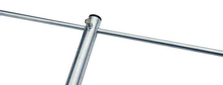
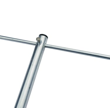
6. Attach the base support insulator to your ground post using the 8 nut clamp aligned with the markings on the insulator. Ensure that the ground post is of sufficient gauge and deep enough to support the antenna safely.
The lower element should be no less than 1m above ground. The ground post can be higher but then antenna mounting and guying will become more challenging.


7. Your co-axial cable can now be fitted to the matching transformer with a PL259 connector. Seal the connector against moisture using the self amalgamating tape. Wrap the tape tightly from the socket to the plug. Form a small loop prior to taping the coax cable to the centre support arm using PVC insulating tape.
Finally, recheck the alignment of the end elements and check that all the main element bolts, matching transformer connection lead nuts and cable tie(s) are tight.
Guying
The I-Pro home is designed to be lifted onto the support insulator rod for operation and lifted off again after use. This means the antenna can be laid flat when not in use to minimise any visual impact on neighbours.
For extended use, particularly in exposed areas, it is recommended that the I-Pro home is guyed with 3 x 6m lengths of 3mm nylon cord (do not use wire). Attach the guy lines just above the centre support arm clamp with one line pulling opposite to the support arm (and feeder) and the other 2 at 120 degree spacing (either side of the matching transformer). The feeder can now be adjusted to trail away at between 30 and 45 degrees to the vertical.
A guying ring is provided and a full guying kit is available from Pro Antennas.
Support
proantennas@gmail.com
+44-7470 337050
© 2025. All rights reserved.